<tfoot id="ey0o0"></tfoot>
Water Meter Solution
Jiannan Machinery has been an intelligent product service provider for over 50 yearsLocation:Home / Solutions / Water Meter Solution / Smart Water Solutions
1. Company Profile
Huaihua Zhixin Energy Technology Co., Ltd. is a wholly-owned subsidiary of Huaihua Jiannan Machinery Factory Co., Ltd. The registered capital of the company is 51.8 million yuan. It is a high-tech private enterprise in Hunan Province, mainly engaged in the research and development, production, and sales of smart water meters and smart meters.
The company adheres to the military tradition and military quality, and is committed to the research and production of intelligent instruments and meters. As of now, the company's annual production capacity of electric energy meters has exceeded 5 million units, and the production capacity of water meters has exceeded 1 million units.
Huaihua Jiannan Machinery Factory Co., Ltd. was founded in 1970, formerly known as the state-owned Jiannan Machinery Factory (Military Industry 4507 Factory), which is a large state-owned military technology enterprise. In 2007, the company underwent a state-owned enterprise restructuring, asset restructuring, and equity changes, and was renamed Huaihua Jiannan Machinery Factory Co., Ltd.
The development of the company has received attention and importance from leaders at all levels of the country, ministries, and provinces. State leaders such as Zhao Ziyang, Jiang Zemin, Hu Jintao, and Zhu Rongji have personally inspected and guided the company. The company has always adhered to the core business philosophy of "creating value for customers and winning survival through innovation", promoting enterprise development with technology, surpassing customer expectations with quality, continuously strengthening product and service innovation, and striving to create a first-class instrument supplier.
2. Comprehensive analysis of smart water management
2.1 Overview
Smart water management utilizes new generation information technology and combines sensor technology, networks, and mobile systems with water information systems to build a comprehensive water management system that includes intelligent perception, simulation, diagnosis, warning, scheduling, disposal, control, and services. Smart water management "is an important component of smart city construction, aimed at improving the level of water management and services, providing better support for urban development, and effectively enhancing urban smart construction and livability
2.2 Trend analysis
According to the "2015 Report on the Current Situation and Development Trend Analysis of China's Smart Water Market" released by China Industry Research Network, on April 16, 2015, the highly anticipated "Water Pollution Prevention and Control Plan" was released, and the water market in China will generate a growth of 5 trillion yuan. In the next 5 to 10 years, the Chinese water market will present an unprecedented explosive pattern. Faced with such fierce competition, how to establish oneself as the foundation and have industry core competitiveness has become a topic that water companies are thinking about or exploring! So, as a traditional water industry, can it take advantage of the new trend of "Internet plus" technology "Internet of Things, cloud computing, big data" to take off in the wind of "Internet plus Water"?
The 2015 edition of the China Smart Water Industry Market Status Research and Development Trend Analysis Report conducted in-depth research and analysis on the current situation, development changes, and competitive landscape of China's smart water industry, and elaborated on the future development trends of the smart water market. It also made a cautious judgment on the future development prospects of the smart water industry based on its development trajectory, providing new investment highlights for investors in the smart water industry.
3. Solution
3.1 User side Solution
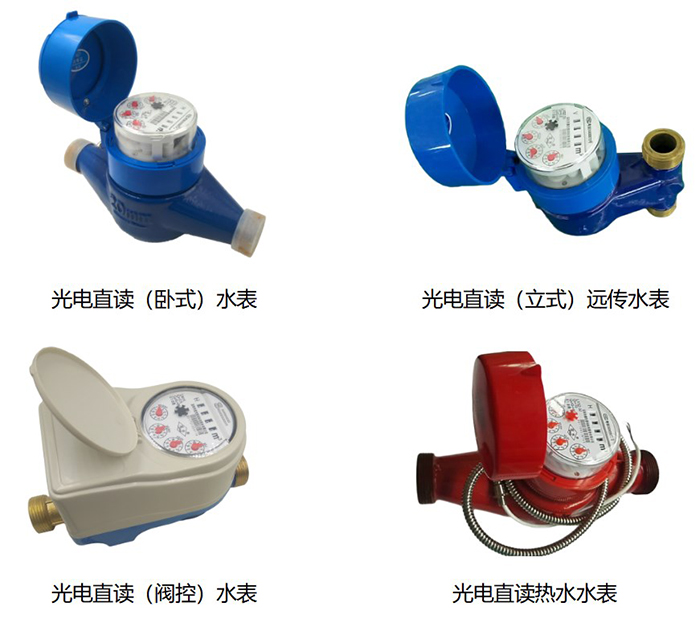
3.1.1 LXSZ type photoelectric direct reading wired remote water meter
3.1.1.1 Overview
The LXSZ direct reading wired remote water meter (hereinafter referred to as the direct reading remote water meter) is a self-developed direct reading remote water meter that is convenient for remote meter reading and control, designed to meet the practical needs of daily water use. It adopts M-BUS/RS485 bus communication to achieve remote direct reading of water meter usage, effectively avoiding the need for management departments to come to the door for meter reading. This product also has valve control function (optional), which facilitates the management department to control the water usage of the direct reading remote water meter, making remote meter reading and control more convenient and reliable. While saving manpower, material resources, and financial resources, it effectively improves productivity.
This direct reading remote water meter complies with the technical requirements of GB/T778-2007 "Measurement of Water Flow in Closed Full Pipelines - Drinking Cold Water and Hot Water Meters" and CJ/T224-2012 "Electronic Remote Water Meters". The communication protocol follows the requirements of CJ/T188-2004 "Technical Conditions for Data Transmission of Household Measuring Instruments" or DL/T645-1997 "Communication Protocol for Multi functional Electric Energy Meters", and can also be customized according to customer needs.
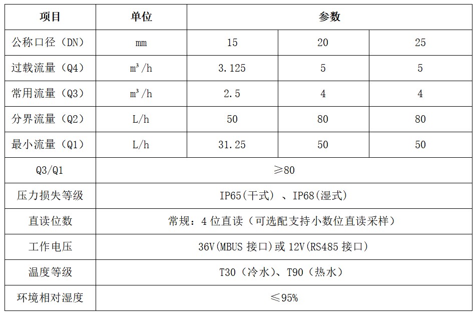
3.1.1.2 Water meter flow parameters
3.1.1.3 Performance Characteristics
Directly reading the window value of the meter, not cumulative pulse conversion, without cumulative error.
The meter is passive, there is no battery inside the meter, it has zero power consumption during normal operation, and the direct reading device only works when powered on at the moment of meter reading.
The direct reading meter has a unique address code, which ensures that the address is unique and correct.
Real time collection of water meter data, not pulse accumulation metering, no initialization required. The system does not require table initialization during the first activation or after troubleshooting and restarting, greatly reducing the workload of maintenance.
Passive photoelectric remote water meters directly transmit digital signals instead of pulse signals. It is not only unaffected by mechanical vibrations, but also not afraid of magnetic interference, so it can achieve stable, accurate, and reliable measurement in complex usage environments.
The entire system does not operate normally and does not provide power. It only operates during the moment of meter reading, resulting in extremely low power consumption. There is no need for built-in power or backup power, and maintenance is simple. Data will not be lost due to power outages or network failures.
Adopting MBUS or RS485 bus communication, the construction difficulty is low, the construction cost is low, the debugging is simple and easy, the carrying capacity is strong, and the equipment cost is greatly reduced. After the installation of the line and water meter, meter reading can be completed.
The direct reading data is the real-time display value of the remote transmission meter wheel window, just like visual inspection with the naked eye. The system reads the data absolutely accurately, completely solving the problem of carry and misread of other direct reading meters. The system meter reading data always maintains zero error with the remote transmission meter display value. Therefore, when the water meter reverses, the automatic meter reading data is consistent with the reading of the water meter meter words.
3.1.2 Lora photoelectric direct reading wireless remote water meter
3.1.2.1 Overview
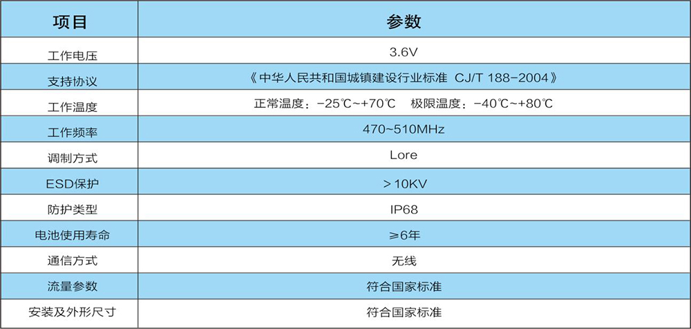
Lora wireless remote transmission photoelectric direct reading water meter is a self-developed remote reading water meter that is convenient for remote meter reading and control, designed to meet the practical needs of intelligent management in water supply companies. It adopts our company's direct reading water meter sampling principle as the measurement basis, and communicates with the collector/concentrator through the low-power application free measurement frequency band (470-510MHz). The concentrator uniformly communicates with the main station through the GPRS module to upload the data to the main station, realizing automatic remote reading of water meter usage. It supports bidirectional communication, real-time on-off valve, real-time point reading, and the meter end is normally in low-power mode. When the concentrator issues the meter reading command, the water meter at the designated address wakes up and performs meter reading. After completion, it continues to enter low-power mode, effectively reducing the power consumption of the meter end. This product also has valve control function (optional), which facilitates the management department to control the water usage of the water meter, making remote meter reading and control more convenient and reliable. While saving manpower, material resources, and financial resources, it effectively improves production efficiency.
Lora wireless remote reading water meter meets the technical requirements of GB/T778-2007 "Measurement of Water Flow in Closed Full Pipelines - Drinking Cold Water Meter and Hot Water Meter" and CJ/T224-2012 "Electronic Remote Water Meter". The communication protocol follows the industry standard CJ/T 188-2004 for urban construction in the People's Republic of China.
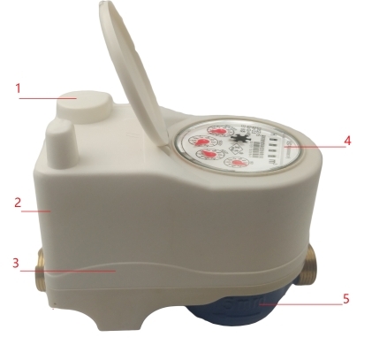
3.1.2.2 Functions of Main Components
1. Power supply battery: mainly used to store batteries for disassembly;
2. Force trigger switch: used to trigger the wake-up of the table terminal during debugging;
3. Through hole ball valve (optional): It is mainly used to control the closing and opening of tap water flowing through the meter under the control of the main circuit board.
4. Optoelectronic direct reading sampling module: mainly used for sampling measurement data;
5. Basic meter: mainly used to measure the current water consumption;
3.1.2.3 Functional Features
This product is based on our company's very mature and stable direct reading sampling, and the reading accuracy can reach 100%.
This product is equipped with a through-hole ball as a valve at the outlet end of the body to reduce the impact of the valve on the measurement. This function is optional.
The electronic reading device does not affect the measurement accuracy of the original instrument.
This product adopts an IP68 protection design, which completely isolates all electrical components such as the circuit board, power supply battery, actuator motor, etc. from the external atmosphere.
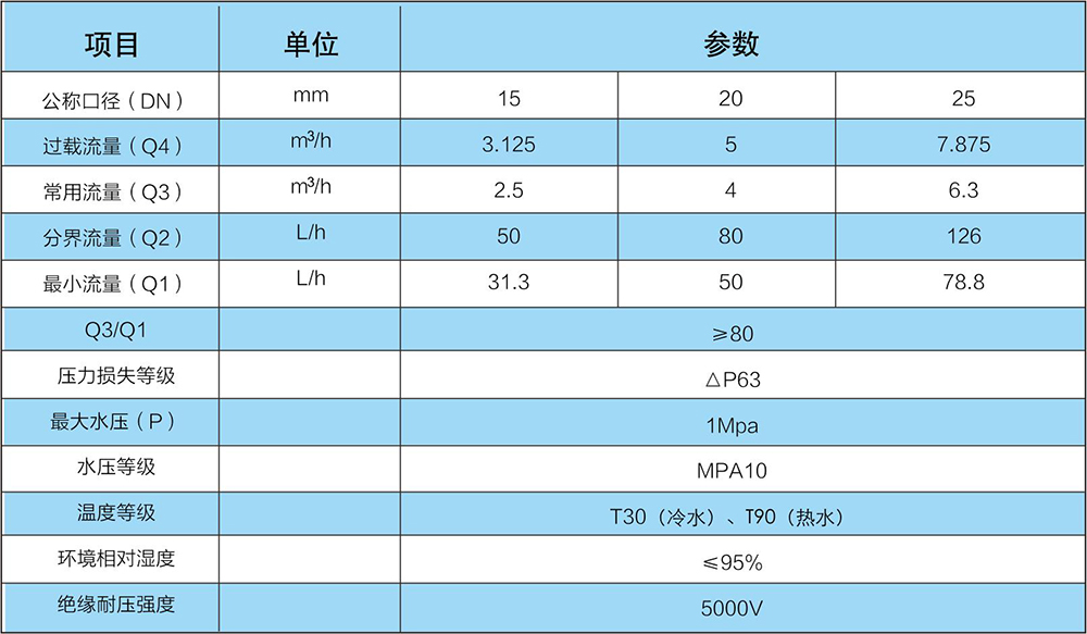
3.1.2.4 Technical indicators
3.1.2.5 Electrical parameters
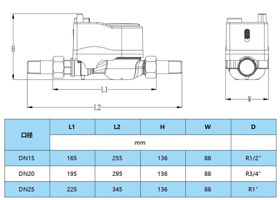
3.1.2.6 Installation diagram and dimensions
3.1.3 NB IoT Optoelectronic Direct Reading Meter Network Remote Transmission Water Meter
3.1.3.1 Overview
NB IoT remote reading water meter is a remote reading water meter developed by our company, which is convenient for remote meter reading and control. Using our company's direct reading water meter as the measurement basis, we use NB IoT narrowband cellular IoT for IoT to achieve automatic remote meter reading of water meter usage, effectively avoiding the need for management departments to come to the door for meter reading. With valve control function (optional), it facilitates management departments to control the water meter usage, making remote meter reading and control more convenient and reliable. While saving manpower, material resources, and financial resources, it effectively improves production efficiency, especially suitable for installation in environments with difficult wiring and sparse population.
NB IoT remote reading water meter, in compliance with the technical requirements of GB/T778-2007 "Measurement of Water Flow in Closed Full Pipelines - Drinking Cold Water Meter and Hot Water Meter" and CJ/T224-2012 "Electronic Remote Water Meter". The communication protocol follows the protection level IP68 specified in the "130 Communication Protocol Specification" and the "GB4208-2008 Standard Specification".
3.1.3.2 Core Functions
1. Remote reading: Proactively report readings on a periodic basis.
2. Remote valve control: can remotely close and open valves.
3. Prepaid: Supports prepaid and pre order quantities, and closes the valve for overdue payments.
4. Warning system: Alarm prompts such as battery undervoltage, abnormal metering, pre order quantity, and pre paid usage reaching threshold. Different emergency water usage can be set according to different users.
5. Large capacity storage: can freeze data for up to 24 months and 31 days per day.
6. Step by step water price: Water prices can be set at different benchmark prices and step by step prices based on user categories and usage.
3.1.3.3 Functional Features
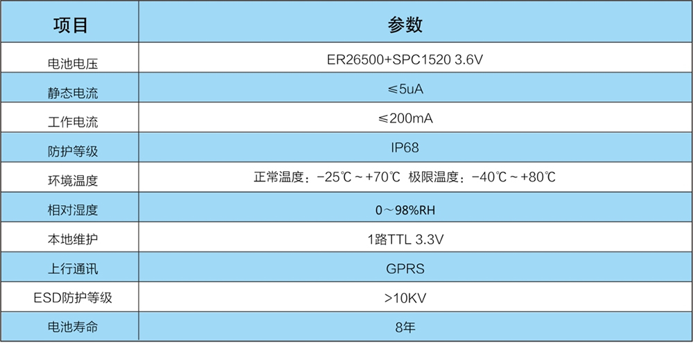
Ultra long life combination battery: Standard ER26500 battery+SPC1520 battery capacitor combination power supply guarantees 8 years of use without replacement.
■ Internal/External Antennas: Supports internal/external antennas, stable and reliable signals, achieving full coverage without blind spots.
High accuracy of direct reading sampling: Based on our company's direct reading water meter remote transmission, the reading accuracy can reach 100%.
Flexible upload frequency setting: The data upload cycle can be set to meet the management needs of different users.
■ Protection level IP68: Protection level IP68, suitable for various complex environments.
The modular structure design and maintenance of electronic units are more convenient.
The system adopts BS architecture: there is no need to install a client, just log in through a browser, and it can be supported on both PC and mobile phones.
This product is based on our company's very mature and stable direct reading sampling, and the reading accuracy can reach 100%.
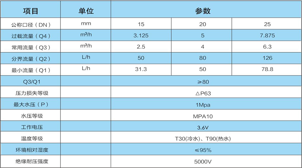
3.1.3.4 Technical indicators
3.1.3.5 Electrical parameters
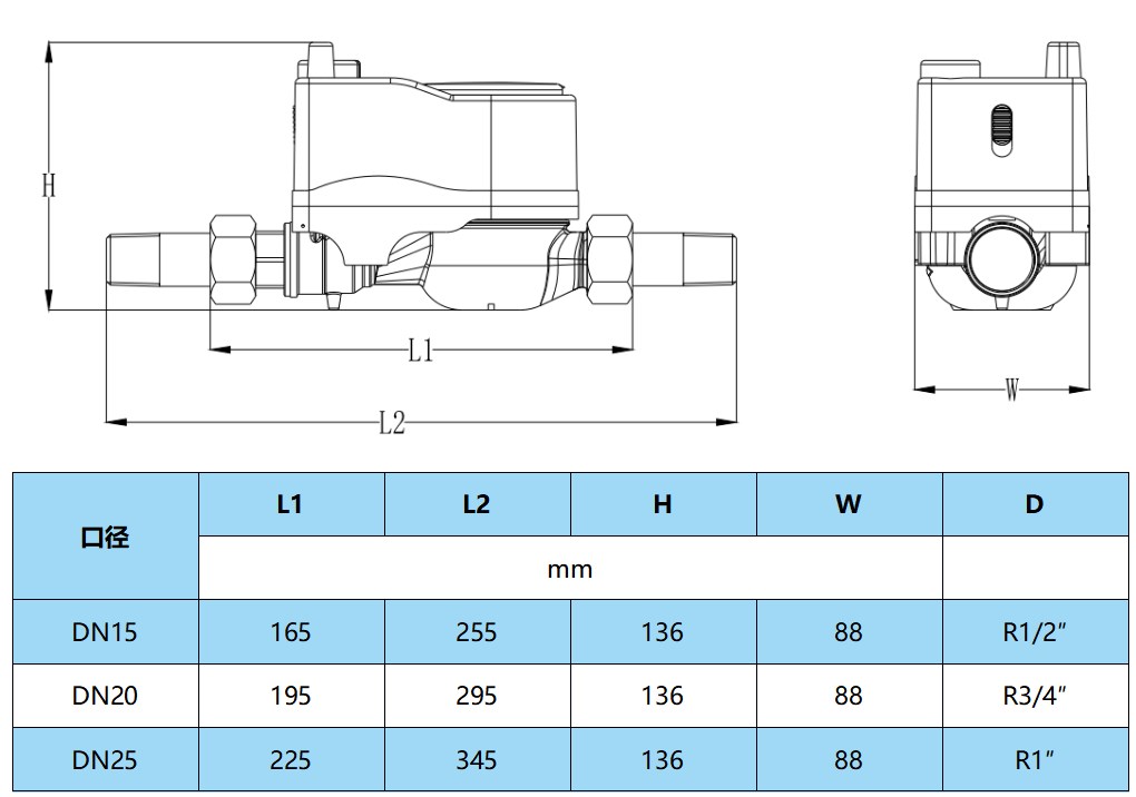
3.1.3.6 Installation diagram and dimensions
3.1.4 IP IoT remote transmission direct reading water meter
3.1.4.1 Overview
The IP IoT remote direct reading water meter (hereinafter referred to as IP water meter) is a self-developed remote water meter that is convenient for remote meter reading and control, designed to meet the practical needs of intelligent management in water supply companies. It adopts our company's direct reading water meter as the measurement basis, and automatically communicates with the network through GPRS or SMS to achieve automatic remote meter reading of the water meter usage, effectively avoiding the need for management departments to come to the door for meter reading. This product also has valve control function (optional), which facilitates the management department to control the water usage of the water meter, making remote meter reading and control more convenient and reliable. While saving manpower, material resources, and financial resources, it effectively improves production efficiency.
This IP water meter complies with the technical requirements of GB/T778-2007 "Measurement of Water Flow in Closed Full Pipelines - Drinking Cold Water and Hot Water Meters" and CJ/T224-2012 "Electronic Remote Water Meters". The communication protocol follows the requirements of CJ/T188-2004 "Technical Conditions for Data Transmission of Household Measuring Instruments", and can also be customized according to user needs.
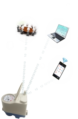
3.1.4.2 Functional Features
Remote reading: Proactively report and read readings on a periodic basis.
Remote valve control: can remotely close and open valves.
Prepaid: Supports prepaid and pre order quantities.
Warning system: Alarm prompts such as battery undervoltage, abnormal measurement, pre order quantity and prepaid usage reaching threshold, etc., can be set according to different users for different emergency water usage.
Large capacity storage: Freeze data for up to 24 months.
Step by step water price: Water prices can be set at different benchmark prices and step by step prices based on user categories and usage.
GPS positioning: GPS geographic positioning, easy to manage.
3.1.4.3 Performance advantages
Ultra long life combination battery: Standard battery capacitor combination power supply ensures 6 years of use without replacement.
■ Internal/External Antennas: Supports internal/external antennas, stable and reliable signals, achieving full coverage without blind spots.
High accuracy of direct reading sampling: Based on our company's direct reading water meter remote transmission, the reading accuracy can reach 100%.
Flexible upload frequency setting: The data upload cycle can be set to meet the management needs of different users.
■ Protection level IP68: Complies with the international standard IEC529 for protection level IP68.
The modular structure design and maintenance of electronic units are more convenient.
The system adopts BS architecture: there is no need to install a client, just log in through a browser, and it can be supported on both PC and mobile phones.
3.1.4.4 Functions of Main Components
■ Power supply battery: mainly used to store batteries for disassembly.
GPRS antenna: mainly used to place the GPRS module antenna.
Case: mainly used to install measurement and acquisition modules, circuit boards, and valve control motors inside it.
Optoelectronic direct reading sampling module: mainly used for sampling measurement data.
Basic meter: mainly used to measure the current water consumption.
■ Through hole ball valve (optional): mainly used to control the closing and opening of tap water flowing through the meter under the control of the main circuit board.
3.1.4.5 Technical indicators
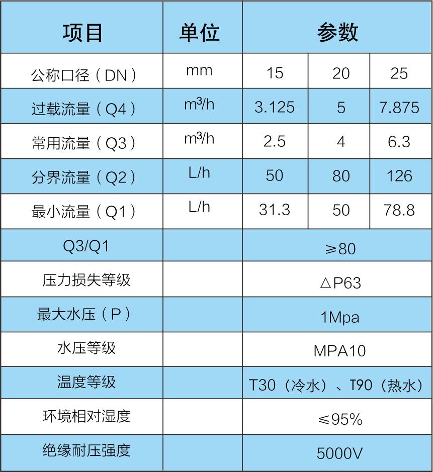
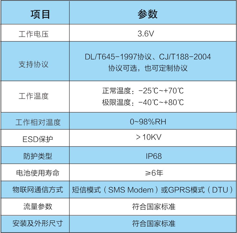
3.1.4.6 Electrical parameters
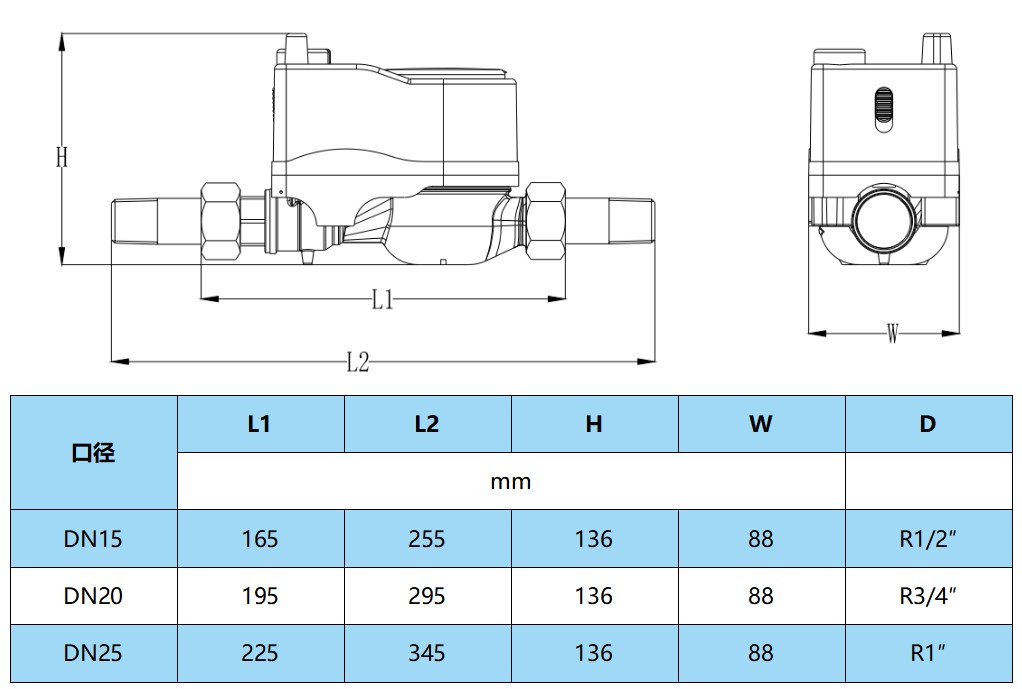
3.1.4.7 Installation diagram and dimensions
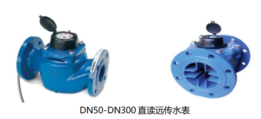
3.1.5 Optoelectronic direct reading large-diameter remote water meter
3.1.5.1 Product Introduction
The horizontal and vertical spiral wing series large-diameter direct reading remote water meters use photoelectric direct reading sampling technology to directly read the current dial reading, with a meter reading accuracy of 100%, and have the characteristics of high reliability, high precision, and low power consumption.
3.1.5.2 Working principle (photoelectric character wheel encoding direct reading mode)
Principle: Through transmissive photoelectric conversion, the position and status of the counter wheel are instantly read by meter reading. Using the principle of photoelectric encoder, each wheel is treated as a code wheel, and five infrared receiving tubes sense the level changes caused by the infrared light emitted from the transparent groove on the wheel to form a set of five digit numbers. After decoding, the numbers are transmitted to the system computer for display on the meter reading interface, which is the same as the window value of the water meter.
3.1.5.3 Functional Features
The photoelectric coding direct reading scheme ensures accurate and reliable measurement data;
When powered by an external power source, electronic remote transmission function can be achieved;
Using DL/T 645 communication protocol makes it more convenient to build a centralized meter reading system;
M-BUS/RS485 bus design, with stronger on-site anti-interference capability;
■ Size: The nominal diameter, nominal flow rate, length, connecting thread, and flange of the water meter shall comply with the provisions of Table 1 or Table 2 in GB/T778.1-1996 "Cold Water Meter Part 1: Specification".
Data lead out specifications: RVV2 * 0.3 mm, length of 100 cm, two core waterproof sheathed wire, core wire is multi strand wire, and the cable is covered with a metal hose.
3.1.5.4 Technical indicators
■ Interface type: RS485, MBUS, TTL optional;
Measurement level: Level 2;
Single meter reading time: ≤ 800ms;
■ Transmission distance: ≥ 1200m;
Communication transmission rate: 1200kps;
■ Working power supply: DC12V ± 2V;
Electronic reading accuracy: 100%;
■ Shell: ductile iron;
Sampling method: photoelectric coding direct reading;
Rated power consumption: ≤ 1mA when powered, ≤ 12mA when read;
This product has IP68 waterproof standard.
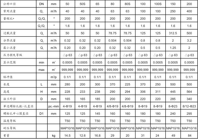
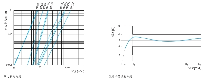
3.1.5.5 Parameters related to large-diameter water meters
LXLGY horizontal spiral wing structure for direct reading of large-diameter water meter parameters
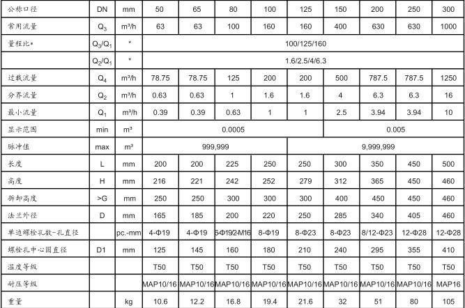
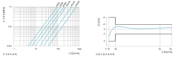
■ Vertical spiral wing structure for direct reading of large-diameter water meter parameters
3.1.5.6 Product Features
The structural design of the WS vertical spiral wing water meter is compact, simple, and reasonable, without a worm gear transmission chain, and the impeller directly drives the counter; Simultaneously using a high hardness shaft and its special bearing system, it has low resistance, high transmission efficiency, very low starting flow rate, and greatly enhanced wear resistance. It has the characteristics of wide range, high flow capacity, low pressure loss in high flow areas, and high measurement accuracy in low flow areas;
The counter is sealed with copper and has a waterproof rating of IP68;
■ Built in stainless steel filter screen.
3.2 Data Collection Equipment Solution
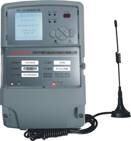
3.2.1 MRC-3000 Data Concentrator
3.2.1.1 Overview
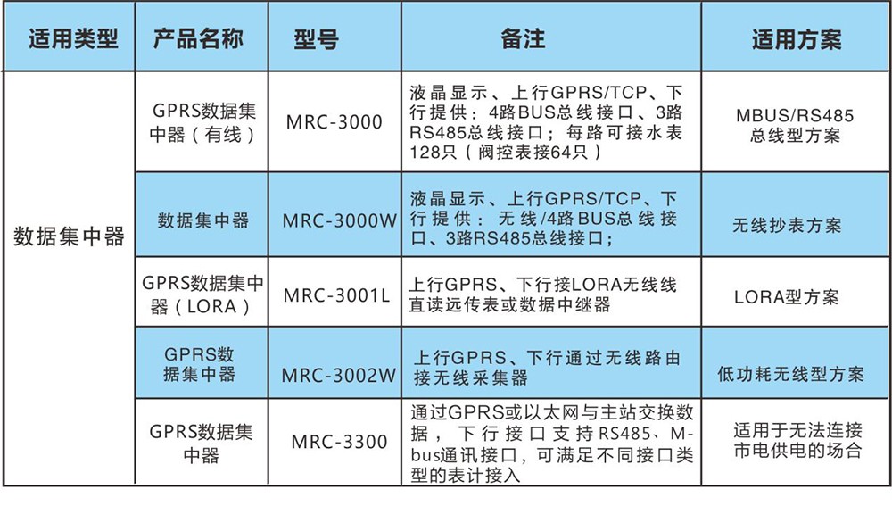
The MRC-3000 data center meter reading terminal adopts a high-performance 32-bit ARM9 core hardware platform, an autonomous embedded operating system, and powerful function expansion and system upgrade space. It can collect and store various data of the water meter through setting or timing, and can exchange data with the main station through GPRS or Ethernet. It has a large data running space of 64M SDRAM and 128M Nand Flash data storage space, which can ensure that data can be saved for 10 years without loss after power outage. The terminal adopts a large screen LCD display and is equipped with communication interfaces such as infrared, RS485, M-Bus, and wireless, which can meet various meter reading modes such as mounting collectors and directly mounting meters. A complete self recovery circuit design ensures the normal operation of the equipment and prevents crashes. This terminal adopts advanced ultra-low power large-scale integrated circuit technology, and key components are selected from internationally renowned brands of long-life devices, which improves the reliability and lifespan of the product.
3.2.1.2 Functional Features
Data collection and processing function: It can call for real-time testing or automatically collect remote transmission meter related data information according to the set reading interval.
■ Scheduled automatic collection: The concentrator automatically collects data from remote meters based on the meter reading scheme set by the main station.
■ Copying function: The data concentrator mainly completes the collection and monitoring of remote transmission meter data, and uploads these monitoring data to the monitoring center (main station) through wireless (GPRS, CDMA, GSM) or wired (Ethernet, etc.) channels. And it has the function of receiving commands from the control center for real-time full and random copying.
■ Setting function: It can set automatic meter reading cycle, reading interval, reading interval, etc., and measures to prevent unauthorized personnel from operating.
■ Extended function: It can receive commands from the control center or freeze the accumulated amount of the water, gas, and heat meters in real-time according to the set freezing time.
■ Timing function: The concentrator adopts high-precision real-time clock chips, which can accurately record the current time. The daily timing error of the timing unit is ≤ 1S/d. It supports remote timing by the main station and keeps the terminal consistent with the main station at all times.
Control function: Can receive commands from the control center to control the opening and closing of prepaid users.
Wireless remote communication function: The concentrator is embedded with GPRS/CDMA/GSM wireless data communication modules.
Data storage function: The storage system of the concentrator adopts an 8M SPI FLASH electronic disk. Can save various data for a long time.
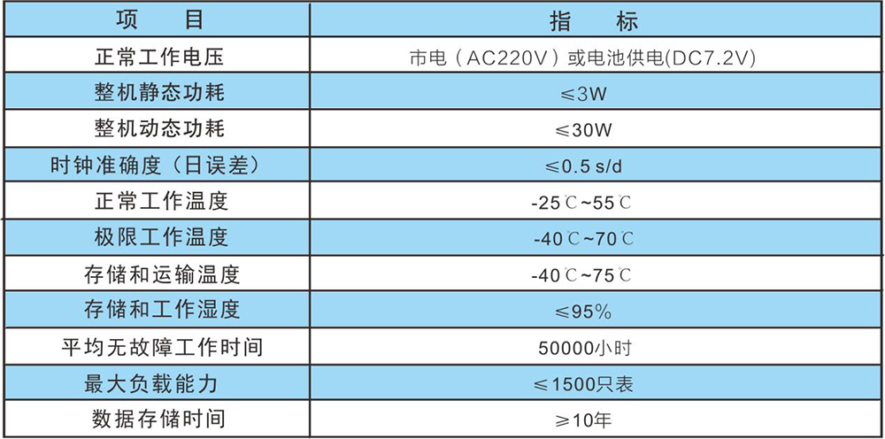
3.2.1.3 Technical Parameters
3.2.1.4 Drawing
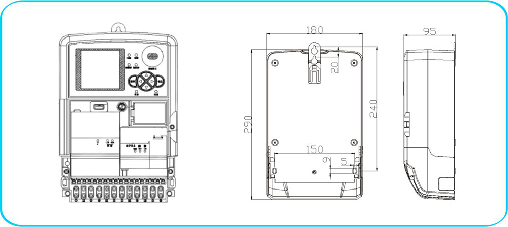
3.2.1.5 List of Concentrator Types
3.2.2 DCT-2500G Data Collector
3.2.2.1 Overview
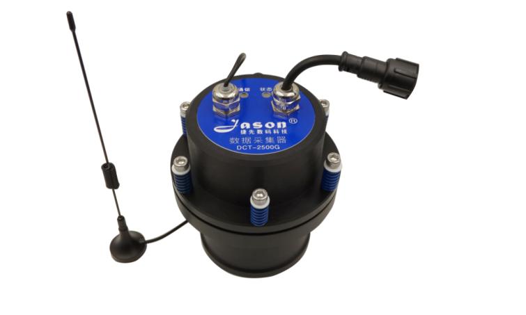
The DCT-2500G data collector is based on monitoring equipment and uses public network (GPRS) wireless communication technology and modern sensor technology to collect, store, and transmit large-diameter remote water meter flow data and pressure sensor data.
3.2.2.2 Functional Features
Transfer device data to the platform system through GPRS (China Mobile or China Unicom can both) network access;
Equipped with high-performance suction cup antenna, ensuring that the data collector can communicate normally in the pipeline well;
It can collect RS485 remote transmission data of large caliber water meters, pressure transmitters, and remotely control valve switches on pipelines. The communication protocol supports 645 protocol and 188 protocol;
The data collector collects and stores data from remote water meters according to the user's set cycle. The cycle is from 1 minute to 1 day, measured in minutes, with a default of 5 minutes;
The data collector sends the data recorded during the sending cycle to the data center server through GPRS wireless communication technology according to the user-defined cycle. Sending cycle options: 1 hour, 6 hours, 24 hours, default is 6 hours;
The sending cycle starts from the sending reference time, and every other sending cycle time, the data collector starts GPRS to send data. The sending reference time can be set arbitrarily;
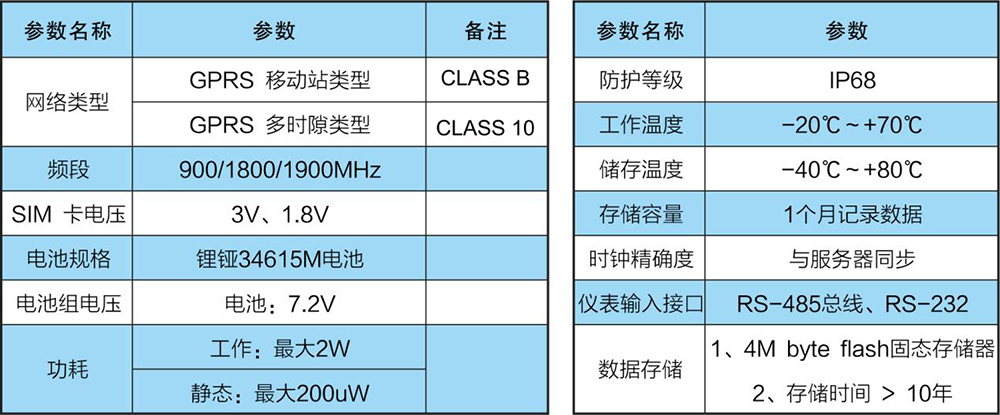
The data collector is powered by 4 high-power lithium argon batteries. By default, when working (communicating every 6 hours), the battery has a one-time service life of more than 8 years;
The data collector can be remotely configured through GPRS. Equipment configuration can also be done using a computer through 485 communication.
3.2.2.3 Performance Parameters
3.2.3 DCT-2001 Data Collector
3.2.3.1 Overview
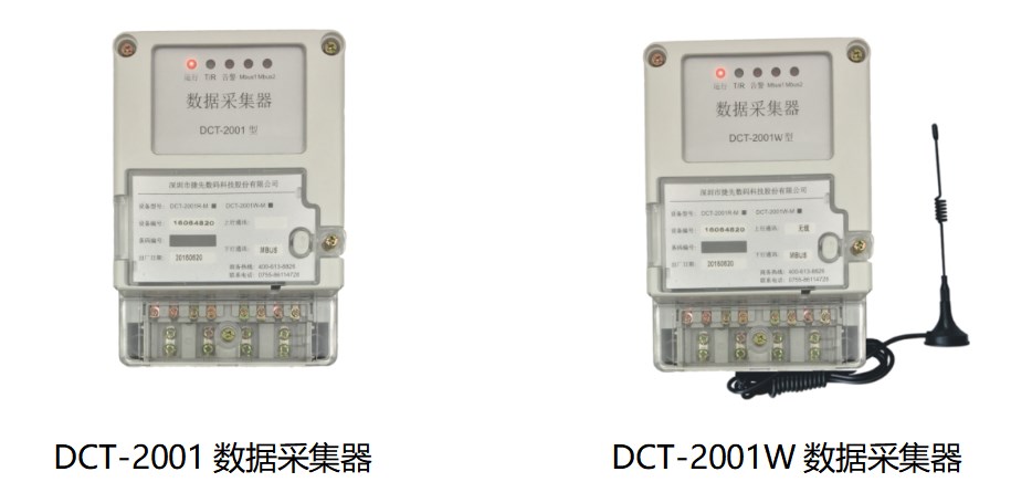
The DCT-2001 data collector is a specialized expansion device developed by our company for intelligent network meter reading systems such as water meters, gas meters, and heat meters. Each output port leads to an expansion bus, which connects to the meter. The system controls the on/off of the water meter power supply and reads meter data information through addressing to achieve centralized meter reading and standalone meter reading. This product also has functions such as lightning protection, bus isolation, fault indication, overload protection, and short circuit protection.
3.2.3.2 Functional Features
The system accesses the meters in the corresponding data collector output channel through addressing, without affecting the operation of meters in other data collector output channels.
Channel output expansion, providing real-time power supply and data communication for the channel meter during network data transmission;
Amplifying the signal of the communication link can extend the network transmission distance and increase the network load capacity.
Only supplying power to the downstream meter during meter reading reduces the overall power consumption of the system and has strong anti-interference ability.
It can automatically test the load condition of the downstream Mbus channel, with short-circuit and overload indication functions, and cut off the faulty channel to ensure that the equipment is not damaged.
The data collector is powered by an industrial grade switch power supply, which has the characteristics of a wide input voltage range, high output power, and high power efficiency.
The DCT-2001W data collector and data concentrator are wirelessly connected to reduce construction difficulty.
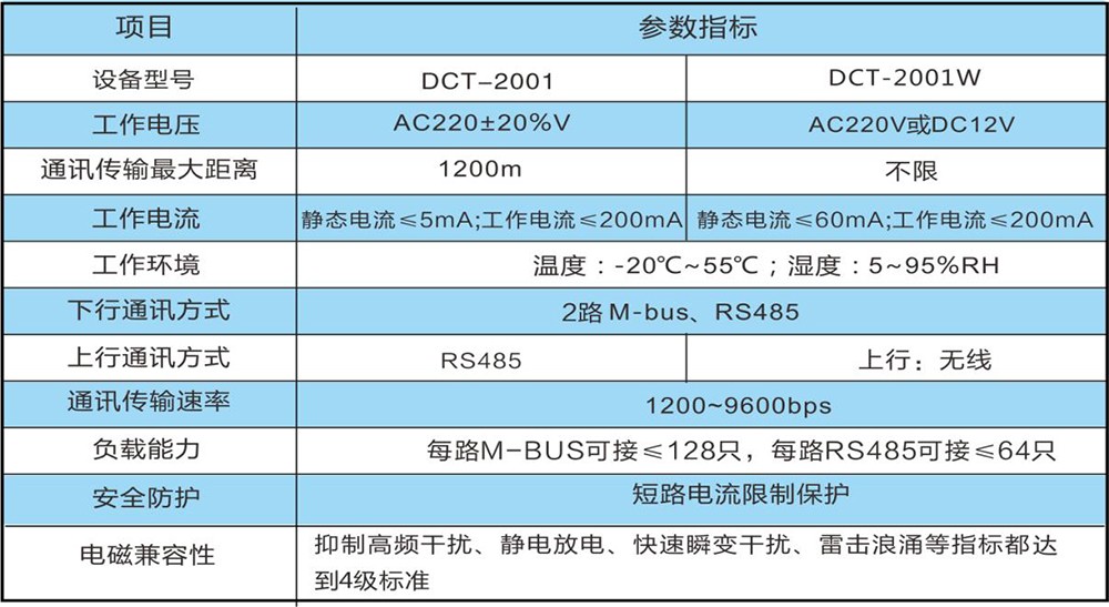
3.2.3.3 Electrical Parameters
3.3.4 DCT-2300M/R IoT Acquisition Terminal
3.3.4.1 Product Introduction
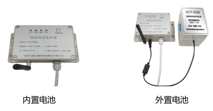
The DCT-2300 series IoT collection terminal (hereinafter referred to as the terminal) is an intelligent network meter reading device that combines IoT technology (2G IoT module or NB IoT module), ultra-low power consumption technology, and intelligent meter reading. It is powered by batteries and is particularly suitable for meter reading situations where power and wiring are difficult; Meter reading time and reporting cycle can be set separately. This terminal adopts a high-performance 8-bit ultra-low power MCU hardware platform, with an internal expansion of 512 Kbit EEPROM data storage space, which can collect and store various data of the water meter at regular intervals. Upstream communication exchanges data with the main station through GPRS wireless remote transmission. The downlink interface can be connected to RS485 meters or M-bus meters.
3.3.4.2 Product Features
Ultra low sleep current during abnormal operation to ensure battery life;
Through GRPS wireless remote meter reading, there is no spatial distance limitation;
Flexible selection of different battery capacities to determine meter reading quantity and service life, supporting external or internal battery power supply;
It has functions such as low battery voltage alarm and overload judgment based on the number of meters;
■ It can be operated by importing meter files locally, debugging, and setting parameters;
■ The device can be awakened at any time by pressing the wake-up button to enter working mode;
Wall mounted, with good sealing of the shell;
■ It has indicator lights for operation, network, meter reading, and other functions, making it convenient for debugging and use.
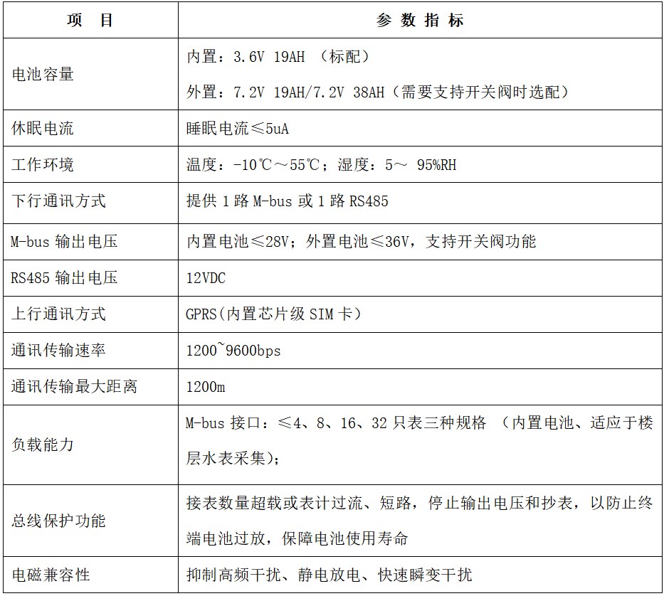
3.3.4.3 Technical parameters:
3.3.5 DCT-2310M/R IoT Acquisition Terminal
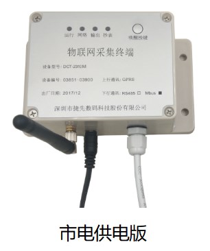
3.3.5.1 Product Introduction
The DCT-2310 series IoT collection terminal (hereinafter referred to as the terminal) is an intelligent network meter reading device that combines IoT technology (2G IoT module or NB IoT module) and intelligent meter reading. It is powered by a power adapter and is suitable for automatic meter reading in unit buildings or management meters with a count of up to 128 meters; Support real-time online meter reading, with separate settings for meter reading time and reporting cycle. This terminal adopts a high-performance 8-bit ultra-low power MCU hardware platform, with an internal expansion of 512 Kbit EEPROM data storage space, which can collect and store various data of the water meter at regular intervals. Upstream communication exchanges data with the main station through GPRS wireless remote transmission. The downlink interface can be connected to RS485 meters or M-bus meters.
3.3.5.2 Product Features
■ Powered by a power adapter, supporting real-time online meter reading;
Only outputting voltage to power the meter during meter reading, reducing the overall power consumption of the system and having strong anti-interference ability;
■ It has the function of judging overload based on the number of meters;
■ It can be operated by importing meter files locally, debugging, and setting parameters;
■ The device can be awakened at any time by pressing the wake-up button to enter working mode;
Wall mounted, with good sealing of the shell;
■ It has indicator lights for operation, network, meter reading, and other functions, making it convenient for debugging and use.
3.3.5.3 Technical Parameters
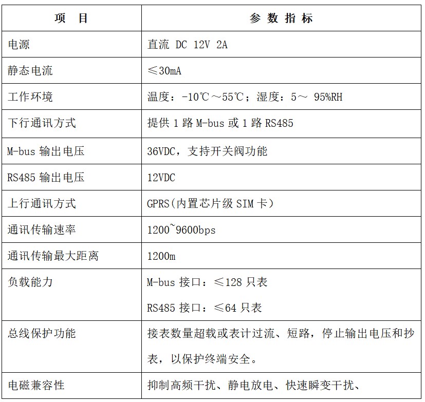
3.3.5.4 Main functions
Wireless remote communication function: The terminal is embedded with GPRS or NB IoT wireless data communication module, which uses GPRS wireless data service for terminal data communication;
■ Scheduled data collection and storage: Automatically collect and freeze meter data according to the set time cycle, and actively report data;
■ Status detection and alarm function: The terminal has various intelligent detection, analysis, and automatic alarm functions for abnormalities, and can actively report abnormal information to the main station;
■ Status indication function and button function: It has terminal operation and wireless communication status indication function and button function.
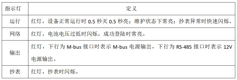
When the terminal enters maintenance mode and cooperates with on-site debugging software, various parameters of the terminal can be set, such as the main station IP address and port number IP, terminal address, downstream meter reading type, meter file import, etc;
When the terminal enters maintenance mode and cooperates with on-site debugging software, various information of the terminal can be queried through the meter reading interface, such as version, alarm information, main station IP address, and port number.
3.3.5.5 On site installation and debugging
■ Appearance and installation dimensions
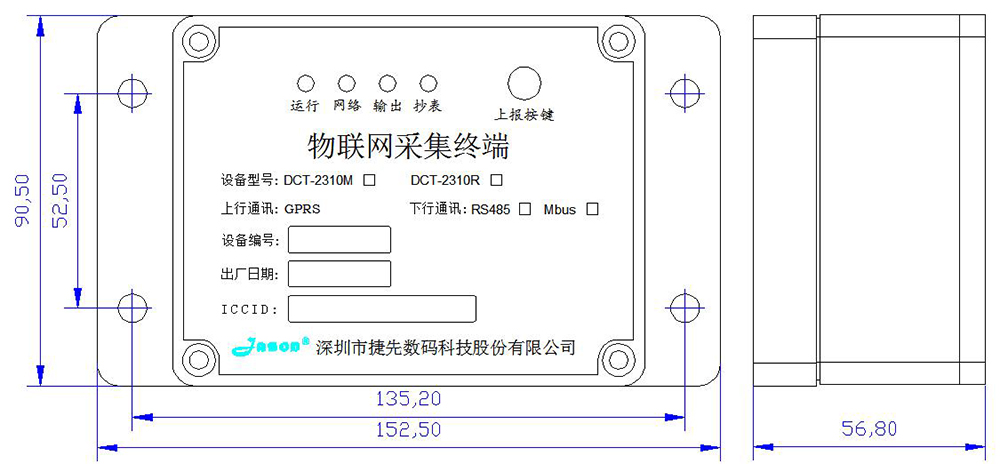
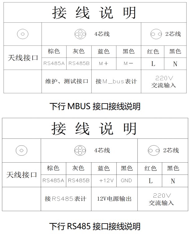
■ Wiring Instructions
3.3.5.6 Key Functions:
Press the report button three times within 5 seconds to enter the active reporting state. If the terminal already has a meter file, it will directly enter the meter reading state. At this time, the meter reading light will flash once every time the meter reading is performed. When the meter reading light no longer flashes, it indicates that the meter reading is completed and enters the data reporting process. After successful communication with the main station, the network light will remain on.
3.3.5.7 Terminal maintenance function
Press and hold the report button for 5 seconds until the status indicator light stays on, entering maintenance mode. Through on-site debugging software and meter reading interface, various parameters of the terminal can be set, such as the main station IP address and port number, terminal address, downstream meter reading type, meter file import, etc. At the same time, various terminal information can also be queried, such as version, main station IP address and port number, reporting frequency, maintenance interface type, and other information.
Note that when there is no communication data on the maintenance interface, it will automatically exit within 1 minute and the device will enter normal operation.
3.3.5.8 Parameter Setting, File Download, and Debugging
Long press the report button to enter maintenance mode: Long press the report button for 5 seconds until the status indicator light stays on, then enter maintenance mode. At this time, you can set various parameters and query the terminal, and download files. Attention: The parameter settings have already been configured at the factory, please do not change them unless there are special circumstances.
■ File download: Open the "IoT Collection Terminal Debugging Software" and follow the instructions in the operation manual to import the table configuration file.
■ Table data query: Open the "IoT Collection Terminal Debugging Software" and read the table data according to the operation manual to confirm whether the file is correct.
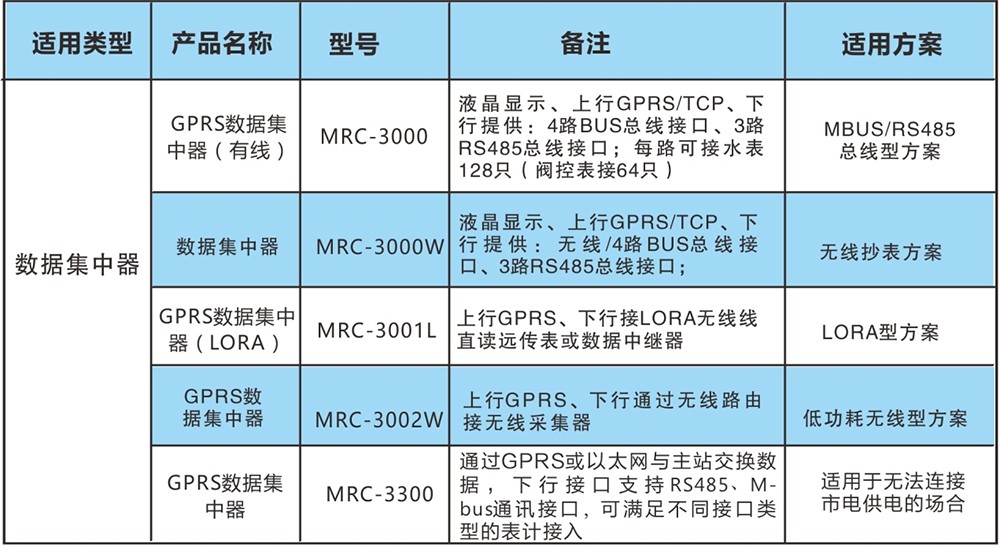
3.3.6 List of Concentrator Types
3.3 Solution for Water Supply Network End
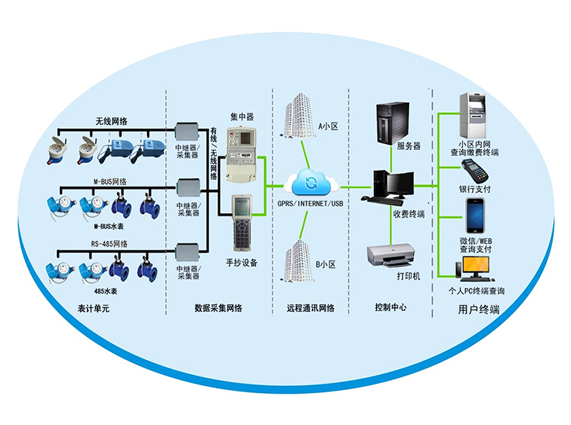
GPRS networking: The main station server, sub station server, service terminal, concentrator require routing, switching, firewall and other equipment, as well as network support from China Mobile and China Unicom network operators.
Ethernet (Local Area Network and Wide Area Network): The main station, servers, and concentrators of the community management need to be connected through devices such as routers and switches. The concentrators must have a fixed IP address, and the main station, servers, and concentrators of the community management need to be connected within the network or remotely.
This system is suitable for water supply enterprises to remotely monitor the water supply network. Staff can remotely monitor the pressure and flow of the city's water supply network from the dispatch center. Scientifically command the start and stop of water supply equipment in each water plant to ensure balanced water supply pressure and stable flow rate; Timely detection and prediction of pipe burst accidents. The SCADA online monitoring system for water supply network is a subsystem of the water supply dispatch management system of the water company, mainly composed of the water company dispatch center, communication platform, monitoring terminal, pressure transmitter, and flow instrument. Real time or scheduled transmission of data, operating status, and alarm signals to the data server via wireless means (GPRS or GMS SMS); By using "remote monitoring management software" to dynamically monitor on-site instruments, timely reminders of abnormal situations on site are provided, and personnel are dispatched to investigate abnormal situations. At the same time, various application reports are provided through the software's various analysis functions, providing strong technical support for reducing production and sales gaps and making reasonable water supply management decisions.
3.4 Information Technology Solutions
3.4.1 Characteristics of Communication Network Technology for Management Stations
3.4.1.1 Transmission System
The secondary network adopts network transmission method. The direct reading intelligent meter to the concentrator uses low-power measurement frequency band (470-510MHz) to transmit data, and the concentrator to the management station management computer uses GPRS network to transmit data, ensuring data synchronization.
3.4.1.2 Management Station Communication System Configuration
The management station can adopt wired or wireless network access methods according to actual needs to ensure stable data transmission. The communication system and network equipment configuration of the management station adopt dedicated communication modules (Ethernet, fiber optic Ethernet, GPRS, INTERNET, etc.) to establish a data transmission network.
3.4.1.3 Data Storage Devices
The data storage of this technical solution adopts centralized storage and distributed storage backup, which can be divided into concentrator end storage, and the data is uploaded to the backend computer management center. Set up a database on the management computer at the management station, which is responsible for storing the measurement data of the tables. The management station database is synchronized with the concentrator data to achieve the purpose of data backup and ensure the secure storage of data.
3.4.1.4 System Security
This communication system consists of a secondary network, and each level of communication system is independent of each other, forming a network through dedicated lines without any interdependence. The systems only need to provide network interfaces to each other, ensuring the advanced security of the entire system.
When there is a public network failure, the management computer of the management station can independently complete data storage and control management work, and store all data. When the network is restored, historical data can be viewed or missing data can be supplemented to ensure data integrity.
3.5 Meter Reading and Charging System Scheme
3.5.1 Overview of the Plan
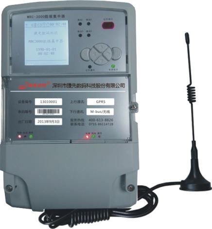
The MRC-3000 data center meter reading terminal adopts a high-performance 32-bit ARM9 core hardware platform, an autonomous embedded operating system, and powerful function expansion and system upgrade space. It can collect and store various data of the water meter through setting or timing, and can exchange data with the main station through GPRS or Ethernet. It has a large data running space of 64M SDRAM and 128M Nand Flash data storage space, which can ensure that data can be saved for 10 years without loss after power outage. The terminal adopts a large screen LCD display and is equipped with communication interfaces such as infrared, RS485, M-Bus, and wireless, which can meet various meter reading modes such as mounting collectors and directly mounting meters. A complete self recovery circuit design ensures the normal operation of the equipment and prevents crashes. This terminal adopts advanced ultra-low power large-scale integrated circuit technology, and key components are selected from internationally renowned brands of long-life devices, which improves the reliability and lifespan of the product.
3.5.2 Functional Features
Data collection and processing function: It can call for real-time testing or automatically collect remote transmission meter related data information according to the set reading interval.
■ Scheduled automatic collection: The concentrator automatically collects data from remote meters based on the meter reading scheme set by the main station.
■ Copying function: The data concentrator mainly completes the collection and monitoring of remote transmission meter data, and uploads these monitoring data to the monitoring center (main station) through wireless (GPRS, CDMA, GSM) or wired (Ethernet, etc.) channels. And it has the function of receiving commands from the control center for real-time full and random copying.
■ Setting function: It can set automatic meter reading cycle, reading interval, reading interval, etc., and measures to prevent unauthorized personnel from operating.
■ Extended function: It can receive commands from the control center or freeze the accumulated amount of the water, gas, and heat meters in real-time according to the set freezing time.
■ Timing function: The concentrator adopts high-precision real-time clock chips, which can accurately record the current time. The daily timing error of the timing unit is ≤ 1S/d. It supports remote timing by the main station and keeps the terminal consistent with the main station at all times.
Control function: Can receive commands from the control center to control the opening and closing of prepaid users.
Wireless remote communication function: The concentrator is embedded with GPRS/CDMA/GSM wireless data communication modules.
Data storage function: The storage system of the concentrator adopts an 8M SPI FLASH electronic disk. Can save various data for a long time.
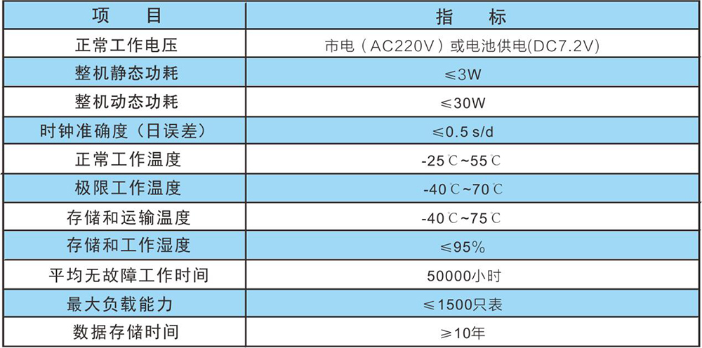
3.5.3 Technical Parameters
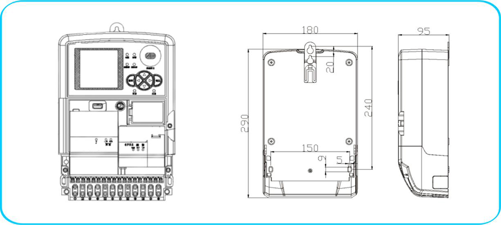
3.5.4 Drawing
0745-2380548
market@hhjnc.com
Hongji Building Changshou Industrial Park Industrial Concentration Zone Mayang Miao Autonomous County Huaihua City Hunan Province
